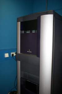
SGI Onyx 2
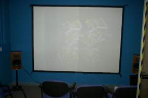
Projection Screen
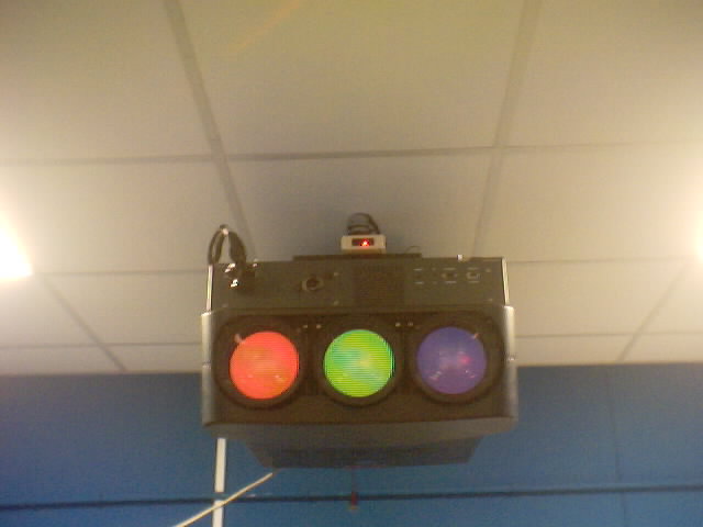
Projector
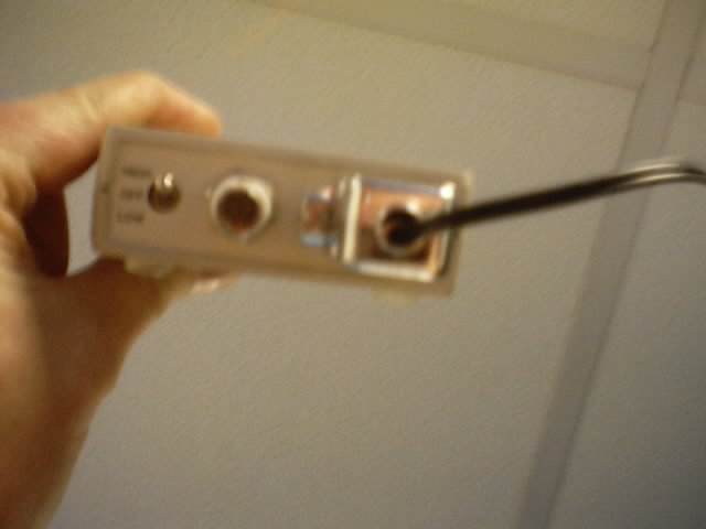
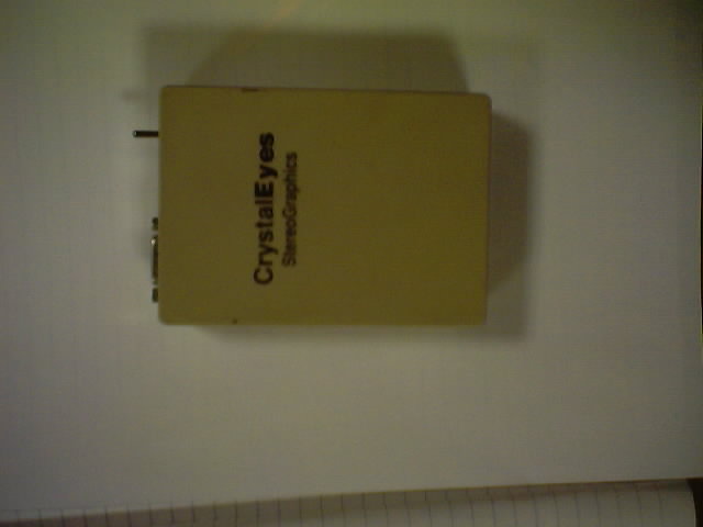
Crystal Eyes Emitter
Last Updated: 12/09/2009
Disclaimer: Use at your own risk
|
This howto explains how to convert your crystal eyes emitter so that it will accept stereo data from a GeForce3 or similar card. Note, for pc games style stereo (i.e DirectX) you simply need to do the conversion and then run your card manufacturers stereo display drivers. You will then be able to use the Crystal Eyes glasses in place of the cheap and tacky ones that generally come with the graphics card. If however, you want to use quad buffered stereo for programs like VMD (http://www.ks.uiuc.edu/Research/vmd/) or 3Space Assistant (http://www.tgs.com/) then you need to install a patched version of the NVIDIA drivers. See http://www.rosswalker.co.uk/stereo/howto1_PatchedDrivers.htm for details. 1) The Hardware Original Hardware = SGI Onyx 2, Crystal Eyes Emitter Model E-1 Mains Powered Emitter, Crystal Eyes 2 Glasses. |
|
|
|
|
|
|
New Hardware = 1.4GHz AMD, 768MB DDR Ram, 40GB HD, Asus V8200 Deluxe GeForce 3 with Stereo Glasses.
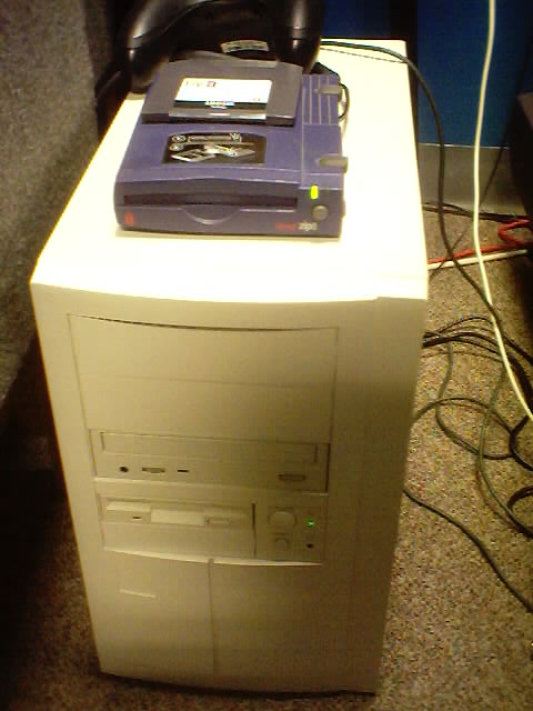 1.4GHz AMD PC |
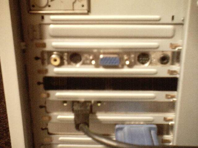 Back of GeForce3 Card |
2) The Theory
The stereo output from the Asus GeForce3 card is in the form of a 3.5mm stereo jack designed to be connected to the Asus wired stereo glasses. The first step was to connect each of the pins from the stereo jack and work out what each pin does.
Unfortunately I don't have pictures of the oscilloscope traces but what you essentially have is the earth connector of the jack providing a constant 1KHz square wave of 10V peak to peak. You then have the middle and tip giving similar 1KHz signals but 180 degrees of out phase with each other. One of these signals is always in sync with the constant 1KHz signal of the earth. Every time the screen completes a vertical refresh a delay of half a cycle is inserted into both the tip and middle 1KHz signals. This has the effect of reversing which signal is in phase with the constant signal and which is 180 degrees out of phase with it.
The result of this is that the left and right eye LCD shutters see a pulse modulated 10V signal that flips on and off at the same frequency as the screen refresh. This gives a shuttering frequency in phase with the screen.
3) The Solution
Writing the above signals in the form of a truth table gives:
So, we have a simple exclusive OR based system. Now, the crystals input is fairly simple. A crystal eyes box has either a 9 pin female serial style connector or a female coax connector or both. In either case only two pins are required for stereo, the other pins are either for power or unconnected. The pin outs are as follows
:
Now, all the crystal eyes system requires is a TTL High signal to pin 1 whenever the left eye should be uncovered. So all we need to do is use an XOR logic circuit to convert the signal for the left eye from the GeForce card into a simple TTL square wave. E.g if we have a monitor with the vertical refresh set to 140Hz then we need a H->L signal on pin 7 (+5v) at 70Hz synchronised with the monitor vertical refresh.
The following circuit converts the signal from the GeForce card into the signal format required by crystal eyes. Note, there are two XOR gates used to reduce noise from the 1KHz GeForce signal. The original design had only 1 XOR gate but the lack of noise filtering resulted in very poor stereo performance.
Note: A NOT gate can be fitted after the final XOR gate if required to reverse the left and right eyes.
Known problems: The use of an RC circuit here creates capacitor charge and discharge curves at the edges of the square wave. This results in a bright band of about 2 pixels at the top of the screen and a dark band, again of about 2 pixels, at the bottom of the screen. This is only a minor cosmetic problem and does not effect the quality of the stereo.
I have a solution for this problem using a J-K flipflop circuit that does not give capacitor charge curves. I will add this to this page when I have time.
Author:
Ross Walker
© Ross Walker, 2002.